Prospective research on permanent magnet hub motor
First. Introduction
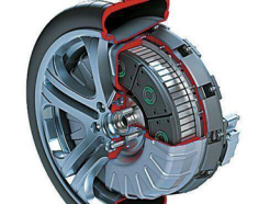
As we all know, hub motor drive technology is an advanced representative of the field of electric vehicles, it integrates the motor, reducer and brake into one, and is directly installed in the rim, making the wheel itself a power unit. This design greatly simplifies the vehicle transmission structure, making it easy to install more battery packs inside the vehicle, while increasing the interior space of the vehicle. However, the system also faces some challenges: first, the spring mass is large, which may affect the handling performance of the vehicle; Secondly, in order to ensure the braking power, the system relies on an electric vacuum pump, which needs to run continuously during the braking process, thus continuously consuming battery power; In addition, the hub motor system is known for its high power density, but it is accompanied by a high loss of power, coupled with limited working space, which poses a challenge to the system heat dissipation; Finally, in view of the complex and changeable working environment, in order to ensure the reliability of the system, more stringent requirements are put forward for the sealing performance.
second, different categories of wheel motor
1, permanent magnet memory wheel motor
Wheel motors face double challenges: to achieve low speed and high torque, but also to ensure high speed and high power, these two needs conflict with each other, it is difficult to take into account. To this end, the permanent magnet memory motor responds by innovative technology. It utilizes the unique irreversible demagnetization characteristics of high remanence and low coercivity permanent magnet materials to flexibly adjust the D-axis current pulse to control the remanence of permanent magnets online and achieve magnetization adjustment. In the full speed range of the wheel motor, the technology can implement a differentiated magnetization strategy for the permanent magnet according to the speed change, thus improving the overall motor performance. However, when the current memory motor is applied as a hub motor, it still faces several major problems: first, the torque density is difficult to reach the level of Ndfeb rare earth permanent magnet motor; Secondly, the wheel motor has higher requirements for overload capacity, and if the magnetic circuit is improperly designed, it is easy to cause demagnetization risk; In addition, although the on-line magnetic control mechanism is effective, it also brings excitation loss, resulting in increased motor temperature rise and impaired system efficiency.
Memory motor can be roughly divided into two categories: AC pulse modulated permanent magnet motor, motor stator winding both drive and control functions, based on vector control mode to adjust the permanent magnet remanence; Dc pulse modulated permanent magnet motor has two sets of windings, namely drive windings and modulated windings, which regulate the magnetic field of permanent magnet by adjusting the size and direction of the excitation current. At present, the research mainly focuses on the double salient pole motor.
Ac pulse modulated magnetic memory motor is mainly divided into single permanent magnet type and hybrid permanent magnet type two. A new type of variable flux motor containing aluminum-nickel-cobalt magnets has been innovatively proposed by researchers at the University of Concord in Canada. Based on the rotor structure of tangential magnetizing permanent magnet motor with magnetic accumulation function, the motor is designed with a special magnetic barrier added on the rotor along the d axis to reduce the saturation phenomenon of the core magnetic field caused by the q axis current, and then enhance the ability to adjust the remanence of the permanent magnet to the armature d axis current pulse. At the same time, combined with the use of high remanence and low coercivity permanent magnet materials, the motor not only achieves a torque density comparable to that of rare earth permanent magnet synchronous motors, but also maintains efficient operation over a wide range of speeds.
2, light rare earth and non-rare earth permanent magnet motor
In vehicles driven by wheel motors, each vehicle usually needs to be equipped with multiple wheel motors, which puts it at a cost disadvantage compared to centralized drive vehicles. In order to alleviate this cost pressure and reduce the dependence on rare earths - a national strategic resource - researchers are working to reduce the rare earth content in permanent magnets, aiming to achieve light rare earth or even rare-earth free permanent magnet motors. However, despite the significant significance of this effort, compared with traditional rare earth permanent magnet motors, such motors still face some challenges when applied as hub motors. Specifically, the lower remanence and coercivity characteristics in the magnet cause the torque density and reliability of the motor to be reduced compared to the rare earth permanent magnet motor, which increases the design difficulty and makes the rotor structure more complex.
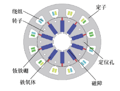
The rare earth permanent magnet motor significantly reduces the use of rare earth permanent magnet materials by replacing some of the rare earth permanent magnet materials with ferrite, or reduces the amount of rare earth permanent magnets by increasing the contribution proportion of the reluctance torque in the total torque. The researchers cleverly combined the hybrid permanent magnet material with the spoke rotor with the concentrated magnetic effect, and successfully developed a less rare earth permanent magnet brushless motor with a power of 5kW. As shown in the figure, the motor can withstand 2 to 3 times the overload, fully meeting the work needs of electric vehicles frequently start and stop. The permanent magnet design of this motor adopts the combination of Ndfeb and ferrite, which not only effectively reduces the use of Ndfeb permanent magnets and controls the cost, but also through the parallel use of two permanent magnets, compared with the use of ferrite alone, not only improves the torque performance of the motor, but also significantly enhances the anti-demagnetization ability of the motor.
Further is the rare-earth free technology, its main technical path focuses on two directions: first, the use of non-rare earth elements to fully replace rare earth elements, especially in the ferrite-assisted synchronous reluctance motor, the electromagnetic torque of this type of motor is mainly contributed by the reluctance torque; The second is switched reluctance motor technology, which completely abandons the dependence on magnets. For ferrite-assisted synchronous reluctance motors, in order to improve the output torque of permanent magnet motors, we can use two strategies: one is to enhance the reluctance torque of the motor, and the other is to optimize the permanent magnet torque, so as to achieve more efficient torque output.
In order to improve the permanent magnet torque of the rare-earth-free permanent magnet motor, the researchers introduced a Spoke-type rotor structure with concentrated magnetic characteristics and a strategy to increase the amount of ferrite material in the motor. Due to the low coercivity of ferrite materials, motor design pays special attention to enhancing its demagnetization ability. The main methods include: (1) By increasing the motor bypass leakage flux path, effectively reducing the demagnetization flux directly passing through the permanent magnet; (2) Reduce the D-axis permeability to improve the salient pole ratio of the motor and thus enhance the torque output performance of the motor; (3) The distributed winding design can effectively reduce the inductance of the motor d axis and optimize the performance; (4) The implementation of the fixed rotor core unequal length structure, and the permanent magnet slightly bulges out of the rotor core, this innovative design not only improves the motor torque, but also significantly enhances the demagnetization ability of the external edge of the permanent magnet - the demagnetization rate of the permanent magnet is reduced to 0.34%, far below the target value of 0.5%, and the maximum torque of the motor is beyond the preset target.
3, stator excitation type permanent magnet motor
The stator excitation type permanent magnet motor successfully solves the problem of permanent magnet cooling in conventional wheel motor by moving rotor permanent magnet to stator side. The rotor uses a common salient pole structure, which is particularly suitable for high-speed operation due to its high mechanical strength. The motor is designed based on the working principle of the switched flux motor, but this feature also brings about the problem of higher current harmonics in the winding, which increases the motor loss, reduces the efficiency, and leads to larger torque fluctuations, affecting the comfort of passengers in the car. At present, the international research on stator excitation type permanent magnet motor is still in the preliminary theoretical discussion and prototype production stage. In contrast, the domestic research is in the initial stage, the main achievements are concentrated on parameter calculation and modeling analysis, and the practical application cases are not rich. According to the different structural forms of the motor, the stator excitation type permanent magnet motor can be subdivided into three categories: flux switching motor, stator permanent magnet mixed excitation double salient pole motor and flux reverse motor.
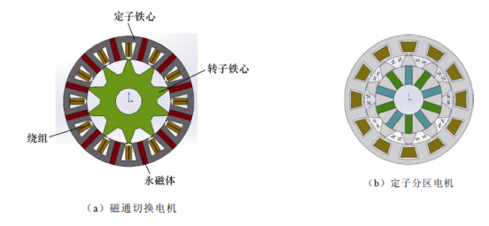
The flux switching motor was proposed by French scholars in 1997. Its topology is shown in Figure a, and its design is simple and easy to control. However, in the case of maintaining the same inner diameter of the stator, there is a mutually restrictive relationship between the winding of the motor and the amount of permanent magnet, which prevents the further improvement of the power density of the motor. In addition, the high degree of saturation of the stator core also has an adverse effect on the operating performance of the motor. In order to solve the problem of mutual restriction between winding and permanent magnet in flux switching motor, researchers innovatively proposed flux switching motor with stator partition structure in 2014. This motor cleverly combines the advantages of a two-stator motor and a flux switching motor. By placing the permanent magnet on the inner stator, the internal space of the motor is optimized, thus effectively alleviating the restriction problem between the permanent magnet and the winding, as shown in Figure b.
The stator permanent magnet mixed excitation double salient pole motor adopts double salient pole structure for its fixed rotor. The rotor is a conventional salient pole reluctance rotor, and the stator yoke is embedded with a radially magnetized permanent magnet. The stator winding is designed in the form of centralized winding, including two sets of armature winding and electric field winding, in which the electric field winding is placed in the slot adjacent to the permanent magnet to adjust the air gap magnetic field, so as to broaden the speed operating range of the motor, and maintain a high operating efficiency in the whole speed range. As a new type of double salient pole permanent magnet motor, which combines the advantages of reluctance motor and permanent magnet motor, the stator core tooth is equipped with a pair of polar permanent magnets, and the rotor is a common salient pole reluctance rotor. The notable features of the motor include: suitable for high speed operation, compact structure, high mechanical strength, small moment of inertia, easy processing, large power density, short motor time constant and convenient commutation.
Third, the noise optimization method of wheel motor
As the core component of distributed drive, the wheel motor has the characteristics of wide speed range and high speed, but at the same time as the electric vehicle part, compared with the traditional engine, there is still harsh noise, in the era of increasing user demand, how to reduce the motor vibration noise is imminent.
1. Motor design
The researchers took 10kW motor as the research object and successfully explored an effective method to reduce the noise of wheel hub vibration. It is assumed that the motor has excellent performance, a maximum efficiency of more than 95%, a rated speed of 500r/min, and a maximum speed of 1500r/min, with a rated torque of 191Nm. For easy installation, the inner diameter and outer diameter of the motor rotor are designed to be 285mm and 320mm respectively. The air gap length of the motor is calculated according to a specific formula.

The length of the air gap is determined to be 2.3mm by calculation considering the overload operation of the electric length and the experience magnetic leakage coefficient. Since the rotor structure includes two kinds of surface mount and built-in, from the convenience of processing and assembly process, the surface mount rotor structure can be preferred because of its simple operation and safe and reliable.
The number of conductors per phase, current, and number of conductors per slot are shown in the following formula. Taking into account the reduction of third harmonics, the motor adopts Y-type wiring.

When selecting the motor pole slot, it is necessary to consider the characteristics of the hub motor directly connected to the wheel, which limits the speed of the motor should not be too high, so the multi-pole motor design is used. In general, an increase in the number of poles will lead to an increase in iron consumption, which will increase the cost of the motor. On the premise of meeting the output demand, it should be inclined to choose a low extreme number to reduce the cost. On the other hand, the increase of the number of slots can effectively reduce the groove torque of the motor, so that the motor is more stable when the load is running. To sum up, it is necessary to determine the best combination of poles and slots through accurate calculation. After analysis, the configuration of 10 poles and 36 slots is the best choice.
It is found that there is a close relationship between the frequency of radial electromagnetic force and harmonics in wheel hub motor. The radial electromagnetic force, as the main cause of electromagnetic vibration of the motor, originates from the interaction between the rotor permanent magnet field and the stator armature reaction field. Based on this discovery, in order to optimize the electromagnetic structure of the motor and reduce vibration, the researchers focused on weakening the radial electromagnetic force, so as to achieve the goal of reducing motor vibration and noise.
Hub motor windings are divided into integer slots and fractional slots. The advantage of fractional slot is that the end is short, the loss is low, and the efficiency is high, but its disadvantage is that it may cause the harmonic magnetomotive force of the motor, resulting in resonance phenomenon. The advantage of the integer slot is that the output torque is large, but the disadvantage is that the number of slots is large and the end span is long, resulting in relatively low efficiency. In view of the limited installation space of the motor and the need to reduce the torque of the tooth groove, the fractional slot winding is usually used.
2. Noise suppression analysis
The frequency range of vibration waves that the human ear can pick up is between 20Hz and 20kHz. The human sense of sound size is proportional to the sound pressure value, so the sound pressure can be used as an objective standard to measure the sound size, replacing the subjective auditory feeling of the human ear. In the process of motor design, engineers need to take reasonable measures according to the noise characteristics of the motor to effectively reduce the adverse effects of motor noise.
The physical measurement of noise produced by motor includes sound power level, sound pressure level, sound intensity level, spectrum curve, loudness and loudness level. When selecting the motor noise simulation model, it is necessary to pay attention to the envelope surface formed by the outer structure of the motor. Based on the analysis of the sound pressure level spectrum curve of the shell observation point, the electromagnetic simulation software is used to design the corresponding cylinder model according to the size of the motor, and the noise propagation in the air is set as the medium to simulate the noise of the wheel motor. The simulation results show that the highest peak of noise is mainly concentrated in the vicinity of 375Hz, 583Hz and 916Hz. According to the national standard and combined with the actual situation of automobile wheel motor, the sound pressure level of wheel motor should be lower than 60dB. However, the motor noise value of the preliminary scheme does not meet this standard and needs to be further optimized.
The rotor structure is divided into two types: built-in type and surface mount type, as shown in the figure. The built-in rotor structure adjusts asymmetrical magnetic circuits to improve motor performance. However, its disadvantage is that the magnetic circuit leakage design is complex, and the built-in processing and assembly process is demanding and difficult. In contrast, the surface mount rotor structure is simpler, the magnetic leakage threshold is low, and the weight of the motor can be reduced under the same output torque.

Compared with the simulation results of the two structures, the rotation pulsation of the surface-mounted motor is 2%, and that of the built-in motor is 6%. The tooth groove torque of the surface mounted motor is 0.4N/m, and the built-in motor is 1.2N /m, so the surface mounted motor is better than the built-in motor.
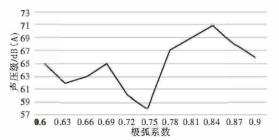
The difference of polar arc coefficient will lead to the change of motor slot torque. In order to investigate how this change affects motor noise, a simulation is carried out to simulate the motor noise caused by torque ripple under different polar arc coefficients. The simulation results are shown in the following figure. It can be seen from the figure that when the polar arc coefficient is 0.75, the motor noise reaches the lowest level. Therefore, 0.75 is recommended as the optimal polar arc coefficient.
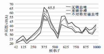
The stator punching slot will change the rotor magnetic circuit, in which the number and size of slots can significantly affect the torque characteristics and noise characteristics of the motor. By comparing the sound pressure level of the non-slot structure with that of the single slot structure, it can be clearly observed that the noise of the single slot structure motor is lower. This is due to the increase of auxiliary slots to help reduce the radial electromagnetic wave, but it should be noted that the width of the slot should not be too small, otherwise the effect is not good. At the same time, the notch should not be too wide to avoid adverse effects on the magnetic circuit. Therefore, the width of the notch is usually set between 1mm and 4mm. The double-slot structure is further subdivided into two types: equal width and unequal width. Among them, the unequal width structure is chosen because it can adjust the magnetic circuit more effectively. In the specific design, the notch size is set to 1.5mm and 4mm respectively. It can be seen from the data in the figure that the motor with asymmetric double-slot structure has the lowest noise in the frequency range below 750Hz.
3, motor performance simulation analysis
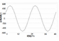
Through the simulation analysis, it can be seen that the magnetic field line and magnetic density distribution of the motor are normal and there is no abnormal phenomenon in the no-load state. The back electromotive force waveform with no load is shown in the figure, and its effective value is 367V. Further decomposing the waveform, we find that the amplitude of the 7th harmonic is the highest, accounting for only 0.73% of the fundamental wave, while the other harmonic components are low. Significant fluctuations in the groove torque will cause the electric vehicle to run unsmoothly, thus reducing the comfort of the ride. By accurate calculation, the proportion of the tooth groove torque to the rated torque is only 0.15%, and its peak value is small, 0.33Nm.
When the load is running, according to the national standard technical requirements of the drive motor system for electric vehicles, the working interval where the motor efficiency is higher than or equal to 80% is defined as the efficient operation area of the motor. For 10kW motor, under the condition of average torque of 190Nm, through calculation and analysis, when the speed is lower than or equal to 1200r/min, the range belongs to the high efficiency zone of the motor, meeting the requirement of efficiency above 80%. Therefore, the above optimization method has been proved to be feasible.
Number four.Future Outlook
The rapid growth of the new energy vehicle market provides a broad market space for the wheel motor industry although the current wheel motor technology is not mature, can not be commercialized on a large scale, but its potential as a future pure electric vehicle drive solution is unlimited. Therefore, it will continue to promote the development of wheel motor technology. Among them, the application prospect of new materials and new processes in the field of wheel motor will be broader. Innovation in material technology is expected to break the limitations of the wheel motor electromagnetic load on the volume and promote the research and development process, including the development of high permeability and low loss magnetic materials, low resistivity conductive materials, efficient thermal insulation materials and low density and high strength structural materials. These innovations will reduce motor losses, reduce mass, and enhance the heat transfer capacity inside the motor, thereby increasing the power and torque density of the hub motor. At the same time, the innovation of the motor process will be based on the existing materials, through a variety of process structure design, to achieve the goal of low loss, lightweight and efficient cooling of the motor.
Note: This article cites data and images from the Internet


