Optimization of insulation performance of fuel cell system
1、 Preface
As the core part of fuel cell vehicles, the insulation performance of automotive fuel cell systems is crucial, which is related to the normal operation of equipment and the safety of passengers. From the perspective of the entire lifecycle, insulation failure of fuel cell systems can be mainly divided into two categories: insulation performance degradation and insulation failure. Insulation performance degradation refers to the gradual failure of insulation measures for system components during long-term operation, resulting in a slow decline in insulation performance and ultimately leading to insulation failure. And insulation failure is caused by non insulation problems of components, which can lead to a sharp decline in the insulation performance of the system. To address these issues, this article elaborates on the design principles and material characteristics of key components such as fuel cell stacks, DC-DC converters, and water pumps, and their impact on system insulation. The rationality of these designs is verified through testing.
2、 Circuit Failure Analysis
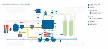
In the fuel cell power generation system for vehicles, the fuel cell stack is the only energy supply component. Its internal design is unique, with the coolant flow channel integrated with the positive and negative electrodes. Therefore, we can explore the issue of insulation failure in fuel cell systems by analyzing the positive and negative electrode circuits, coolant flow channels, and other related components of the fuel cell stack. The high-voltage circuit of the automotive fuel cell system is an important component of the vehicle power supply network. The negative pole of the battery is connected to the chassis, serving as the "grounding point" of the vehicle. It connects the high-voltage cable shielding layer of the fuel cell system, the outer shell of the high-voltage power supply components, and the stack compartment. The high-voltage electricity generated by the fuel cell stack is boosted by a DC/DC converter and supplied to the air compressor, circulation pump, positive temperature coefficient (PTC) heater, water pump, and high-voltage distribution box of the vehicle.
(1)Insulation failure of fuel cell stack
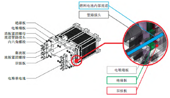
Taking the proton exchange membrane fuel cell stack as an example, its internal flow channel structure is shown in the figure. Among them, the insulation board and pipeline joints are the only non-metallic components with certain insulation properties. When the coolant flows through the end plate of the fuel cell stack, the conductivity will increase, causing voltage to be generated by individual cells in the stack, ultimately leading to leakage. The end plate of the fuel cell stack not only compresses each individual cell, but also plays a supporting and fixing role. However, if the stack is not insulated, the fixed stack can easily be connected to the bracket. In this way, the fuel cell compartment connected to the vehicle's "grounding point" will become electrified, and the insulation performance of the fuel cell will significantly decrease, leading to system insulation failure.
During the assembly process of fuel cell systems, some air may remain inside the fuel cell compartment. When the system is running, this air will form condensed water, which will adhere to the metal surface and corrode the metal and its coating. In addition, condensed water can also adhere to the surface of insulation materials, causing the insulation gap to shrink and the performance of the insulation medium to decrease. Even if the fuel cell stack is in a stable operating state, there will still be a small amount of external leakage during the process. The main sources of leakage include substances such as hydrogen and oxygen. The leakage of these substances not only affects the insulation performance of the system, but also damages its safety performance. During the long-term operation of fuel cell systems, due to the compact arrangement structure and heavy weight of the fuel cell stack, its main body is difficult to withstand stress. Therefore, each individual cell in the fuel cell stack lacks the fastening force constraint of the stack end plate in the horizontal direction, resulting in poor seismic performance. Under complex road conditions, fuel cells are prone to cracking due to seal failure or vibration, resulting in air and water leakage. This not only affects system performance, but may also cause insulation faults.
(2)CVM insulation failure
CVM consists of the connection part, adapter part, and circuit module of the fuel cell stack. The connecting part is directly inserted into the groove of the bipolar plate of the fuel cell stack through a metal plug; The transfer part is fixed using a transfer module and connected to the circuit module through a wire harness. The insulation failure of CVM is mainly divided into two types: wire harness insulation failure and circuit insulation failure. The insulation failure of wire harnesses is mainly affected by the insulation strength of cable wires. During the operation of fuel cells, the potential difference between the positive and negative electrodes of the stack can reach several hundred volts. If the maximum voltage of the fuel cell exceeds the insulation level of the cable, insulation failure is highly likely to occur when the wire harness comes into contact with the fuel cell compartment shell. In addition, when some cables are subjected to strong compression or twisting, the insulation layer is prone to damage, causing the copper core to be exposed and leading to insulation failure.
Due to the excessive emphasis on voltage acquisition function in the design of the CVM module, the insulation of the power supply module, communication module, and signal acquisition module has been neglected. When the bare CVM circuit board is placed in the stack compartment, the circuit board is prone to moisture, which can cause cross zone short circuits and ultimately lead to system insulation failure.
(3) Insulation failure of boost DC/DC converter
Usually, the boost DC/DC converter of fuel cells adopts a multi-channel parallel DC boost circuit. The key components of this circuit include high-power capacitors, inductors, insulated gate bipolar transistor (IGBT) modules, and control circuits. With the continuous improvement of fuel cell system integration, the functions of converters are gradually being developed and perfected. The internal functional topology structure is shown in the figure.

To improve the EMC performance of high-power high-voltage components such as boost DC/DC converters, a filtering circuit can be added to the output of the high-voltage circuit. This can effectively reduce external radiation, alleviate electromagnetic interference, and thus improve the stability of the system. When electromagnetic interference occurs in the circuit, the filtering circuit will enter a continuous charging and discharging cycle. This process will significantly reduce the lifespan of capacitors and inductors. In addition, if the filtering circuit does not match the interference waveform, high-frequency voltage surge signals may cause circuit oscillations. This can cause circuit overvoltage or component overheating, ultimately leading to insulation failure.
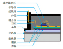
IGBT module is the core component of boost DC/DC converter, and its electrical performance is affected by various factors such as actual production and use environment, design parameters, etc. The internal structure of this module is shown in the figure. After simplifying the insulation circuit, the insulation path between the high-voltage circuit of the IGBT and the grounding point of the boost DC/DC mainly includes thermal insulation adhesive and direct copper coating. The reliability of IGBT is affected by factors such as stress, cycle life, and thermal conductivity. The warpage and residual stress in module packaging have a significant impact on mechanical strength, leading to deformation of the DBC layer. When attached to the heat sink, significant tensile residual stress is generated, which can damage the interior of the DBC layer and affect the insulation performance of the IGBT module. For long-term operation of boost DC/DC converters, the cycle life will affect the metal creep characteristics of the internal solder of IGBT, thereby reducing the solder life. At the same time, the internal resistance of the IGBT bonding wire and the contact area between the semiconductor and copper plate will increase. Overloading of other bonding wires will cause a sharp rise in the internal junction temperature of the IGBT, leading to DBC insulation failure and ultimately triggering system insulation faults.
When DBC experiences insulation failure, an unreasonable IGBT heat dissipation design can cause the junction temperature of the heating module to rapidly rise, damaging the internal structure of the IGBT and thereby affecting its insulation performance. In order to effectively dissipate heat, we use IGBT with insulation thermal conductive adhesive and natural cooling (or water cooling) heat sinks to deal with high-power heat dissipation problems. The insulating thermal conductive adhesive plays a dual role here: it not only transfers heat away from the IGBT, but also provides insulation between the IGBT substrate and the heat sink. We use epoxy resin as the substrate and add alumina particles to make a high thermal conductivity insulation adhesive, which can significantly improve insulation and thermal conductivity. However, if the distribution of insulation thermal conductive adhesive is uneven, or if IGBT is used under high and low temperature cycling conditions, the adhesive may accelerate aging due to uneven heating. In this way, the heat dissipation effect of IGBT will be weakened, and the insulation performance will also be affected.
3、 Analysis of Waterway Failure
The cooling circuit of a fuel cell system consists of two parts: internal circulation and external circulation, and the pipeline flow is shown in the diagram. Among them, components such as the water tank, deionizer, and three-way valve are made of plastic material, which has good insulation properties. The insulation of the fuel cell compartment has been analyzed earlier and will not be repeated here. We can explore the possible paths of insulation failure by analyzing other components in the coolant circuit, such as water pumps, PTC, etc.
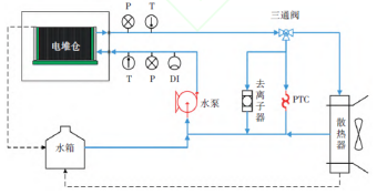
(1)Insulation failure of water pump
The cooling water pump of fuel cell system has the advantages of small volume, large flow rate, high head, and low price. However, the insulation performance of traditional automotive water pumps is poor. In order to suppress the electromagnetic noise generated by the water pump, a filtering circuit is usually added to its power supply terminal (or motor terminal). The insulation problem of the water pump mainly occurs in the following locations:
① The electrodes of the fuel cell flow towards the volute of the water pump through heat exchange fluid. The snail shell of the water pump is made of metal material. When it is connected to the pump casing, the conductivity of the heat exchange fluid increases, causing the pump casing to become electrified.
② At the connection bracket between the water pump casing and the fuel cell system, if the installation bracket of the water pump and the fuel cell system bracket are not insulated, the following situation will occur: Path A will generate high pressure and be connected to the system bracket, resulting in a sharp increase in the electrical conductivity of the heat exchange fluid and a decrease in the insulation performance of the system.
③ The handling of the internal circuit of the water pump is crucial. In order to eliminate electromagnetic noise generated in the control circuit of electronic water pumps, there are two common methods: one is to directly connect the negative pole of the water pump to the housing; The second is to filter the input and output circuits of the water pump. For low voltage powered water pumps, the withstand voltage value of the filtering element is usually set to 50V. However, the conduction potential of the fuel cell electrode to the outside is as high as 400V. If the filtering circuit components of the water pump are in the withstand voltage limit state for a long time, it is very easy to cause accidental connection between the filtering circuit and the housing, which can lead to insulation failure.
In addition, during the long-term operation of fuel cell systems, impurities are prone to accumulate in the coolant circuit, which can block the turbine and rotor of the water pump. Meanwhile, friction can generate high temperatures, making the water pump seals highly susceptible to damage. Once the seal is damaged, the coolant will directly enter the live area of the motor rotor, corrode the coil coating, and cause insulation failure.
(2)PTC insulation failure
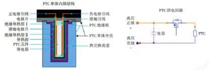
The electric heater PTC consists of three parts: control circuit, heating module, and heat exchange module, and is widely used in the heating system of new energy vehicles. At present, in order to improve the performance of PTC heaters, methods such as improving the louver fin structure and optimizing the positive temperature coefficient parameters are commonly used. The PTC heater used in the fuel cell system is a water heating type, which mainly works by heating the coolant inside the fuel cell stack with high-voltage electricity. If PTC heaters cannot accurately control temperature and heating power, it will lead to temperature fluctuations and energy waste, thereby reducing the performance of fuel cell systems. In addition, the circuit design of PTC faces the same insulation risk as that of boost DC/DC converters. Although direct insertion PTC heaters have high heating efficiency, their insulation performance may be reduced due to the lack of isolation from the heat exchange fluid.
The internal structure of the existing PTC monomer is shown in the figure. A grounding electrode has been added between high-voltage electricity and heat exchange fluid to prevent danger caused by insulation failure. The PTC heating element is tightly attached to the high-voltage power supply electrode, and the high-voltage electrode is connected to the grounding electrode plate through an insulating thermal conductive layer I. If insulation failure occurs in the thermal conductive layer I, it will cause leakage at the grounding point in the high-voltage circuit, leading to insulation failure. Similarly, if insulation failure occurs in the thermal conductive adhesive or insulation thermal conductive layer II, the electrode of the fuel cell will be directly connected to the PTC shell and system grounding point, which will also cause insulation failure. In the case where the electrode potential of the fuel cell stack is about 400V, if the PTC high-voltage direct current directly acts on the insulating thermal conductive layer I and causes it to break down, a short circuit will occur between the fuel cell stack electrode and the PTC high-voltage circuit. This will not only cause damage to the fuel cell stack, but also lead to equipment failure.
4、 Optimize design
Based on the above failure analysis, the current optimization directions include stack optimization, CVM optimization, and boost DC/DC converter optimization
Pump optimization and PTC optimization will be explained separately below.
(1) Optimization scheme for fuel cell stack
The optimization design of the new generation fuel cell stack focuses on the front insulation board, end plate, and piping of the stack, and will be optimized in the following directions:
① Insulation board material. Replace the original epoxy resin glass fiber laminated board with a glass fiber material mixed with polyphenylene sulfide. Compared to the original pressure plate, the new material exhibits excellent hydrophobicity, with no water stains remaining on the cutting surface. The test results show that the resistance values on both the upper and lower surfaces have reached the upper limit of the testing instrument. In addition, the material can withstand the shear stress generated by bolt torque on the shear surface, and is not prone to cracking after being subjected to force.
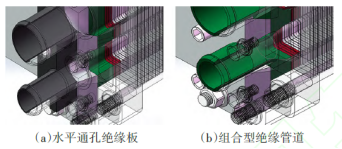
Insulation board flow channel. Replace the horizontal through-hole of the original flow channel with a composite pipeline and adjust the opening structure of the end plate. This modification effectively avoids direct contact between the fluid entering and exiting the fuel cell stack and the stack end plates. At the same time, with the combination of pipes for fixation and sealing, the overall structure has been optimized, as shown in the green part of the figure.
① Electric stack compartment. On the one hand, we have added an air blowing pipeline for the fuel cell stack compartment, which uses dry air to blow out the water vapor inside the compartment to prevent it from condensing into liquid water when cooled, thereby causing insulation material failure. On the other hand, monitoring the hydrogen concentration inside the stack compartment through sensors ensures that the concentration is not too high, thereby ensuring the safety of the stack. Under normal use, the optimized insulation board of the fuel cell stack can ensure that the end plates of the fuel cell stack are not charged. This improvement not only improves the insulation performance, but also simplifies the insulation design between the stack, stack support, and stack compartment bottom plate, reduces the complexity of structural design, and reduces the overall quality of the system.
(2)CVM optimization plan
The optimization of the fuel cell voltage inspection module mainly includes two aspects: circuit design and wiring harness design. In terms of circuit design, the internal circuit of the fuel cell voltage inspection module adopts the dedicated chip 806 developed by an American company, and is equipped with two sets of isolation chips. This combination achieves voltage sampling, power supply, and isolation of circuit board control circuits, significantly improving the insulation performance of the circuit. In terms of wiring harness design, the fuel cell voltage inspection module uses cross-linked polyolefin as the wiring harness material. Compared to traditional polyvinyl chloride, cross-linked polyolefin has improved tensile strength, flame retardancy, and environmental resistance, and is less prone to damage in extrusion environments. In addition, the voltage level of this material can be increased from 60V for low-voltage cables to 450V, further enhancing the insulation performance of the wiring harness.
(3)Optimization scheme for boost DC/DC converter
The boost DC/DC converter of the system will be optimized from two aspects: the filtering circuit and the current conversion unit. In terms of filtering circuit, the filtering circuit of the boost DC/DC converter is mainly composed of resistors, inductors, and capacitors, all of which are connected to the input and output terminals of the converter. When conducting insulation performance testing, parameters such as resistance, inductance, capacitance, etc. can be detected to predict the lifespan of each component and replace abnormal parts in a timely manner to ensure the insulation performance of the system. In terms of current conversion units, in order to reduce the failure rate of IGBT, we have replaced the material of IGBT from silicon-based to SiC with better electrical performance. At the same time, set up an internal thermistor to monitor the heat dissipation performance of the metal connections inside the IGBT. We also use insulating thermal conductive adhesive to bond the IGBT with the cooling channel of the boost DC/DC converter, allowing the IGBT to fully dissipate heat and extend its service life. In addition, by adjusting the proportion of Al2O3 in the epoxy resin, we have improved the thermal conductivity and insulation performance of the insulating thermal conductive adhesive. In current conversion circuits, capacitors and inductors require high-frequency and long-term charging and discharging, resulting in high heat generation. Although they have strong insulation properties, their service life is limited under high-frequency and high current conditions. To avoid internal degradation of components under overheating conditions, it is recommended to monitor the temperature of the heating parts of inductors and capacitors, if conditions permit, to reduce the risk of internal faults in boost DC/DC converters.
(4)Optimization plan for water pump
The insulation performance of the cooling water pump in the fuel cell system will be optimized from the following three aspects:
① Insulation between coolant and water pump housing. In order to isolate the influence of coolant on other components, non-metallic materials can be used for the volute and impeller of the water pump, ensuring insulation performance while reducing the weight of the water pump.
② The water pump control circuit is insulated from the casing. Select components with a voltage resistance exceeding 500V to enhance the voltage resistance of the filtering circuit in the water pump power supply circuit, and to improve the insulation performance of the water pump control circuit, ensuring that the EMC performance of the water pump is not affected. In addition, for water pumps controlled by high voltage (600V) power supply, the voltage withstand level of their filtering circuit needs to exceed 1500V.
③ Insulation between the water pump casing and the system framework. Due to the fact that the casing of the water pump is mostly made of metal material, a shock-absorbing pad with high insulation performance is used between the casing and the system frame, and an insulation board is used when installing the water pump.
(5) PTC optimization plan
The PTC heater of the fuel cell system mainly optimizes the PTC heating element and heat exchange channel. PTC heating elements can use ceramic heating plates, which can improve heat conversion efficiency while significantly reducing their mass and volume. A non-metallic shell with mounting holes has been added outside the heat exchange channel of the PTC heater to prevent direct contact between the heat exchange channel and the fuel cell system bracket. When designing the fixed seat for PTC heat exchange channel and control circuit, the insulation performance of PTC heater is improved by separating the grounding electrode from the heat exchange channel through an insulating gasket. In addition, non-metallic heat exchange flow field plates were used, which not only further improved the insulation performance of PTC, but also reduced the weight of the parts.
Note: The data and images cited in the article are sourced from the internet


