Exploration of the Application of AMR Angle Sensor in Permanent Magnet Synchronous Motor
1、 Preface
At present, the operation of permanent magnet synchronous motors in new energy vehicles mainly relies on position sensors - rotary transformers - to obtain rotor position information. AMR angle sensor is a high-precision, stable and reliable magnetic field sensor that can accurately detect speeds up to 50kr/min. Due to its advantages of low cost and small size, it has gradually become a potential alternative to the rotary transformer in modern new energy vehicle permanent magnet synchronous motors. The sensor provides sine and cosine analog signals, and the magnetic encoder consists of a magnet and a magnetic field sensor installed on the motor rotor shaft. After amplification and digital processing of its output, it tracks the speed and position of the rotating shaft and provides a closed-loop feedback signal. Although AMR sensors can only measure angles up to 180 °, when used in conjunction with sensorless motor position detection technology, it can expand to 360 ° position information. The following text will provide a detailed introduction to the application of AMR angle sensors in motor rotor position detection.
2、 Introduction to AMR angle sensor
(1)Working principle
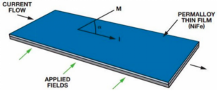
In order to apply AMR sensing units for precise angle measurement, a prerequisite must be met: the magnetization vector M in the magnetic unit must be consistent with the direction of the external magnetic field. This condition is easily achievable. Simply increase the external magnetic field strength acting on the sensor to exceed the internal field of the magnetic field unit, thereby enabling the AMR sensor to enter saturation mode. In this mode, the direction of the external magnetic field is the direction of the magnetization vector M. At this point, the resistance of the AMR sensor depends only on the direction of the external magnetic field, and is independent of the strength of the external magnetic field.
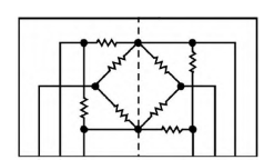
The manufacturing process of AMR sensors involves making four identical sensing units on the same chip to form a Wheatstone bridge. The differential output of this bridge is proportional to sin2 α, where α represents the angle between the current and the direction of magnetization. This means that the angle measurement range of a single bridge is limited to 90 °. The simplified circuit diagram of the dual Wheatstone bridge sensor is shown below, which adopts a dual bridge structure. Due to the arrangement of the two bridge positions at a 45 ° angle, the output signals of the two single bridge sensors will experience a 90 ° phase shift. In this way, a 180 ° angle measurement range is achieved.
The change in resistance can be calculated by the following equation:

In the formula: R - Sensor resistance; R0- Unexcited sensor resistance; Δ R0- Change in sensor resistance; α - the angle between current and magnetization direction.
For AMR sensors, ΔR0 is generally about 3% of the total resistance of the bridge. Due to the minimal change in resistance, a signal amplifier is required to further amplify the output signal to a usable value relative to the power supply voltage.
(2) Axis end angle position detection
AMR based shaft end angle position detection is a position detection method that uses permanent magnets and AMR sensors connected to the rotor shaft end to measure the direction of the magnetic field and determine the position of the shaft. AMR sensor is a high-precision, stable and reliable magnetic field sensor that performs well in dusty and harsh environments. It has no upper limit on magnetic field strength and has high resistance to stray magnetic fields, making it very suitable for harsh electrical environments. When designing solutions, the wide magnetic field strength of AMR sensors brings wider air gap tolerances and greater flexibility. This sensor provides reliable and accurate performance through ferrite magnets, enabling a robust and low-cost solution. In the configuration of the shaft tail magnet, a radially magnetized dipole magnet is located at the tail of the rotating shaft, while the sensor is located below the rotating shaft and the magnet. In this mechanical setup, the north and south poles of the radial magnet form a uniform strong magnetic field above the center of the magnet. As the magnet and motor shaft rotate, the magnetic field also rotates. The arrangement of this sensor ensures that a uniform strong magnetic field is always in the same plane as the detection element.
The configuration of the motor shaft tail magnet is very suitable for the positioning and control of brushless DC motors. For AMR angle sensors, the brushless DC motor used must be an even pole motor, as odd pole motors require complete 360 ° position information. Most closed-loop brushless DC motors use Hall sensors to provide rotor position feedback, thereby determining the accurate position of coil commutation. The accuracy of these sensors is generally between 5 ° and 10 °.
In order to obtain smoother and more efficient motor response and reduce torque fluctuations, we need more accurate motor angle information. Modern AMR sensors have high precision, with a typical mechanical accuracy of ± 0.1 ° and a maximum value of ± 0.5 °. AMR sensors can provide absolute position information under startup or rotor jamming conditions, unaffected by motor position. With the help of this absolute position information, torque can be better controlled, making the motor start more smoothly, while improving starting efficiency and performance when stuck. For permanent magnet synchronous motors, it is necessary to detect the rotor position at 360 °. By using signals generated by bipolar Hall elements to determine the values of sine and cosine signals in different regions, angle measurements from 0 ° to 360 ° can be achieved. In addition, a sensorless approach can also be used to determine the sine and cosine signal values in different regions without the need for additional Hall sensors. In the calculation of magnetic angle, absolute voltage and absolute magnetic field strength are not important. AMR integrated sensors are insensitive to changes in magnetic field strength, voltage amplitude, and drift. In addition, the AMR sensor integrates signal amplifiers, ADC analog-to-digital conversion drivers, and temperature sensors for temperature compensation.
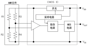
Due to the layout design of two AMR Wheatstone bridges on a single chip, the inherent phase error between the sine and cosine channels can be almost negligible. However, if the output signal is collected through a multiplexed analog-to-digital converter (ADC) without synchronous processing, phase errors will be introduced. Especially when the magnetic field rotation speed is high, the error caused by asynchronous sampling will be more significant because the phase lag between samples will increase. To avoid this situation, it is recommended to use one of the following two methods: one is to use two independent ADCs; The second is to use a multiplexed ADC and two synchronous tracking and holding amplifiers to ensure that the sine and cosine outputs can be sampled synchronously, thereby preventing errors caused by phase lag. The magnitude of the sampling phase error directly affects the size of the calculated electrical error.
3、 Sensorless detection technology for motor position
At present, sensorless position detection technology for motors is widely researched and developed. Most of these technologies are based on the detection of voltage, current, and back electromotive force, and are mainly divided into the following categories.
(1)Using predictive models for measurable voltage or current
Compare the value of the model with the actual detected voltage or current value, and then calculate the difference value, which is proportional to the position of the detected voltage or current value and the actual value. The specific method is as follows: Firstly, construct an accurate d-q model of the motor. Using the detected current for d-q transformation, compare the output voltage of the model with the converted detection voltage. The difference is directly proportional to the angle between the model coordinate system and the actual coordinate system, which reflects the position of the rotor in the actual coordinate system. On the contrary, the current difference can also be obtained by detecting the voltage. Regardless of the method used, the difference between the detection amount and the calculation amount will be used as a multiplier in the rotor position correction equation. However, this method is relatively complex. When the stator parameters change with temperature, it will seriously affect the accuracy of the system. In addition, the algorithm highly relies on mathematical models and positional accuracy, requiring continuous compensation and correction, resulting in a significant computational burden.
(2) Method of using an observer
The more mature method for determining rotor position and speed using an observer is the Kalman filter. As a position measurement tool, Kalman filter can effectively reduce the influence of random interference and noise, and quickly track the actual state of the system. It improves the accuracy of initial estimation of rotor position and speed, but in practical applications, the algorithm is complex and the computational workload is large. In addition to the Kalman filter, commonly used observer systems include nonlinear observers, full order observers, and sliding mode observers. Among them, sliding mode observer is essentially a type of nonlinear observer, characterized by the discontinuity of system control and the flexibility of structure. It can continuously adjust during the dynamic process to make the system operate in the predetermined sliding mode. Sliding mode observers have the advantages of simple structure, few adjustable parameters, fast response speed, and insensitivity to environmental disturbances, thus possessing strong robustness. It is currently a widely used observer in sensorless control.
(3) Modulation signal injection method
The currently mature high-frequency signal injection method is to inject balanced high-frequency voltage or current signals into the three-phase of the motor. These signals utilize the inherent asymmetry within the motor to generate a magnetic salient pole, which in turn detects the corresponding high-frequency current or voltage signal response. In this way, we can obtain the position information and speed of the motor. The high-frequency injection method is mainly divided into three types: rotating high-frequency voltage injection method, rotating high-frequency current injection method, and pulsating high-frequency voltage injection method. Due to the use of an external high-frequency excitation signal to detect convex polarity, this method performs well at low or even zero speeds. Meanwhile, it is insensitive to motor parameters and has strong robustness. Compared to traditional rotary transformers and AMR angle sensors that can only detect 180 ° rotor position information, permanent magnet synchronous motors in new energy vehicles need to achieve 360 ° rotor position detection. The sensorless detection scheme can easily distinguish the position information of 180 ° front and back. Considering that the reliability of AMR angle sensors is slightly inferior to that of rotary sensors, in order to ensure the reliable operation of permanent magnet synchronous motors, the motor can still be driven when the AMR angle sensor fails. Therefore, the sensorless detection scheme combining sliding mode observer or pulse high-frequency voltage injection method becomes the preferred choice. In the application of permanent magnet synchronous motors, AMR angle sensors have cost and volume advantages.
4、 Considerations for magnet selection
(1) Installation of magnets
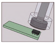
When using AMR sensors, it is necessary to equip them with suitable magnets to achieve optimal performance. Since the direction of the sensor depends on the magnetic field, the magnet used must be magnetized radially rather than axially to ensure that the magnetic field lines point from the north pole to the south pole of the magnet. If it is a shaft tail configuration, the AMR sensor needs to be placed above the magnet (as shown in the figure). At this position, the magnetic field lines can be evenly distributed on the plane where the sensor is located.
(2) Selection of magnet materials
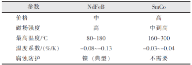
Generally, AMR sensors need to be used in conjunction with rare earth magnets because rare earth magnets have a high magnetic energy to mass ratio. However, as long as the minimum saturation magnetic field strength requirement of the sensor is met, low-cost ferrite magnets can also be used. However, for high-performance and high-temperature applications, the use of rare earth magnets can enhance performance, as AMR sensors can sense higher magnetic field strengths. A higher magnetic field strength can also reduce the impact of stray magnetic fields on sensor accuracy. The two most common materials for manufacturing rare earth permanent magnets are neodymium (NdFeB) and samarium cobalt (SmCo). The following table compares the main advantages of these two magnetic materials. Please note that both materials have multiple grades, so the table is only a rough comparison. To understand the specific characteristics, it is necessary to examine the materials of each level separately. The grade of a magnetic material represents its magnetic energy product, measured in million Gauss Oersted (MGOe), which is equal to the maximum value of the BH curve of the magnetic material. Usually, materials with twice the MGOe value have twice the tensile strength of magnets of the same size. For AMR technology, magnets with higher strength always perform better than magnets with lower strength. Adding AMR sensor components can not only sense higher magnetic field strength, but also improve device performance. However, due to physical limitations, all AMR sensors have high-order harmonics. The AMR sensor with an arc-shaped structure can reduce the fourth harmonic and achieve similar performance at lower magnetic field strengths.
5、 Matching of magnets and sensors
Mechanical alignment is crucial for improving the performance of AMR sensors. When designing, it is necessary to strictly control the x-y alignment tolerance between the magnet and the sensor to ensure that the sensor accurately perceives the direction of the magnetic field. The physical alignment error between the sensor center and the magnet center can introduce systematic errors, which are closely related to the size and consistency of the magnetic field around the sensor. Therefore, the center of the magnet shaft of the controlled shaft tail system must be precisely aligned with the center of the magnetic sensor. In addition, the air gap or z-spacing is equally important for the performance of AMR sensors. Although its importance is slightly lower in absolute alignment than in x-y relative position, it is still necessary to understand the air gap parameters in order to maximize sensor performance. To achieve the rated performance of AMR sensors, the magnetic excitation design needs to provide at least the minimum magnetic field strength required by the sensor, typically 25kA/m. Reducing the working air gap can improve the magnetic field strength perceived by the sensor, but it should be noted that the magnetic field strength will become uneven when approaching the surface of the magnet. An important feature of AMR technology is its insensitivity to air gaps: as long as the sensor reaches complete saturation under the excitation magnetic field, its output angle information will not change with the strength of the magnetic field. This means that small displacements in the z-direction caused by vibration, stress, or lifetime mechanical drift have minimal impact on angular accuracy. The displacement tolerance depends on the material and geometric dimensions of the magnet, and may reach several millimeters to over one centimeter. In the motor shaft tail or off-axis configuration, the magnetic field strength needs to remain uniform throughout the entire mechanical rotation process, and the strength needs to exceed 25kA/m to fully saturate the sensor and overcome internal magnetization effects. On this basis, the output amplitudes of the sine channel and cosine channel need to be synchronized with a phase difference of 90 °. This output synchronization ensures that the radius remains constant under constant temperature conditions. The radius can be calculated using the following formula:

When the radius VRAD is monitored by an external processor or electronic control unit ECU, any significant deviation from the rated radius indicates a system malfunction. Real time mechanical failures, alignment errors, and decreased magnetic field strength can all be monitored by calculating this radius.
6、 Future development and challenges
Although AMR angle sensors have achieved significant results, there are still some challenges and limitations in their performance and application. Future research directions will mainly focus on the following aspects:
(1) Further optimize the performance of AMR angle sensors: By optimizing the material selection and preparation process of magnetic thin films, optimizing structural design and manufacturing processes, and adopting advanced signal processing technologies, the sensitivity, resolution, and stability of AMR angle sensors can be further improved.
(2) Expanding the application fields of AMR angle sensors: With the continuous advancement of technology and the increasing demand for applications, the application fields of AMR angle sensors will become more and more extensive. In the future, the application of AMR angle sensors in biomedical, aerospace, industrial automation and other fields can be further expanded.
(3) Research on new AMR angle sensors: With the continuous development of materials science and micro nano technology, new AMR angle sensors can be studied, such as nano material based AMR angle sensors, flexible substrate based AMR angle sensors, etc., to meet the needs of different application scenarios.
Note: The data and images cited in the article are sourced from the internet


