The Journey of Ideal Cars to the World
Ideal Automobile Enters Globalization: The First Overseas R&D Center Settles in Munich, the "Capital of Automobiles"
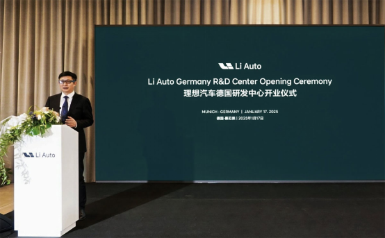
In January 2025, Ideal Auto opened its first overseas research and development center in Munich, Germany, demonstrating the company's continued efforts to increase overseas sales and globalization goals. Ideal Auto stated that the goal of the R&D center is to collaborate with European component manufacturers to develop next-generation technologies, including those related to artificial intelligence, power semiconductors, intelligent chassis systems, electric transmission systems, and overall vehicle design.
Munich is an important center of the global automotive industry and is known as the 'Capital of Automobiles'. As the headquarters of BMW Group, this place not only gathers top-notch automotive research and development technology, but also nurtures a large number of innovative designs. Munich has a well-established automotive industry chain, advancing in various fields from high-precision manufacturing to intelligent driving research and development. In addition, Munich holds multiple international car exhibitions every year, providing a platform for communication and cooperation in the global automotive industry, further consolidating its leading position in the automotive industry
What is the significance of establishing research and development institutions for domestic cars in Germany?
After establishing research and development centers in Beijing and Shanghai, Ideal Auto has opened its first overseas research and development center in Munich, Germany, demonstrating the company's continued efforts to increase overseas sales and globalization goals.
The establishment of a research and development base for Ideal Automobile in Munich, Germany has significant strategic importance. Munich, as the core area of the global automotive industry, gathers a large number of world leading automotive technologies, design concepts, and high-end talent resources. Chinese automobile companies choosing to establish research and development bases here not only have close access to the cutting-edge demands of the European market, but also have in-depth exchanges and cooperation with top German and global automobile manufacturers, thereby enhancing their technological strength and brand influence. In addition, by integrating abundant local research and development resources, Chinese automotive companies can accelerate the development of intelligent, electric, and green low-carbon technologies, helping themselves move towards the high-end of the global automotive industry value chain. At the same time, this layout also indicates that Ideal Automobile is transitioning from "going global" to "integrating", laying a solid foundation for its further development in the global market and demonstrating Ideal Automobile's ambition and strength on the international stage.
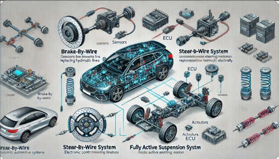
Research on next-generation cutting-edge chassis technologies such as SiC power modules, wire controlled braking, wire controlled steering, and fully active suspension
Ideal Auto announced that it has successfully developed the first generation of silicon carbide (SiC) power modules in China and plans to collaborate with a German R&D team to develop the next generation of power semiconductor technology. SiC power module is the core technology of the new generation of electric vehicles, which has high efficiency, low energy consumption, and high temperature tolerance. It can significantly improve the performance and endurance of electric vehicle power systems, while reducing charging losses. It is an important foundation for promoting the development of new energy vehicles.
The German R&D team will focus on supporting the research and development of chassis wire control technologies such as wire controlled braking, wire controlled steering, and fully active suspension. Brake by Wire and Steer by Wire use electronic signals instead of traditional mechanical connections to achieve more precise control and dynamic adjustment, laying the foundation for intelligent and autonomous driving. And fully active suspension provides passengers with higher driving stability and comfort by adjusting the vehicle suspension response in real-time.
Ideal Automotive Silicon Carbide (SiC) Power Module
Ideal Automobile is actively expanding into the field of silicon carbide (SiC) power modules, which is closely related to industry development trends and has a profound technological background. As a typical representative of third-generation semiconductor materials, silicon carbide power semiconductors have a unique wide bandgap structure formed by the close bonding of silicon atoms and carbon atoms through specific covalent bonds in their crystal structure. Compared with traditional silicon materials, the bandgap width of silicon carbide is about three times that of silicon, which gives it a higher breakdown electric field strength, allowing silicon carbide power modules to withstand higher voltages, usually up to 1200V or even higher, while silicon-based power modules can generally only withstand voltages of around 600V.

What is a silicon carbide power module?
As a globally recognized next-generation semiconductor material that can replace silicon, silicon carbide has the characteristics of high breakdown field strength, high saturation drift rate, and high thermal conductivity. Silicon carbide (SiC) power modules are a key technology in the field of electric vehicles (EVs), gradually replacing traditional silicon-based power modules due to their significant advantages in improving the efficiency of electric drive systems, reducing vehicle weight, and optimizing thermal management.
Silicon carbide (SiC) power modules have become one of the key breakthroughs in the core technology of electric vehicles due to their high efficiency, high voltage endurance, and excellent thermal management performance. Compared to traditional silicon-based modules, SiC modules have lower switching losses, higher operating frequencies, and power densities, while maintaining stability in high temperature and high pressure environments. These advantages make it widely used in key systems of electric vehicles, including inverters, on-board chargers (OBC), DC-DC converters, and e-Drive systems. In these systems, SiC modules significantly improve energy conversion efficiency, reduce device size, and extend vehicle range
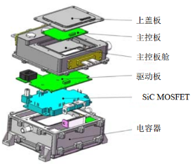
Composition of Silicon Carbide Controller
What is the cost-effectiveness of silicon carbide power modules compared to traditional silicon-based power modules?
In terms of cost: (1) Initial purchase cost: Typically, the price of silicon carbide power modules is higher than that of traditional silicon-based power modules. The total cost of 48 silicon carbide MOSFETs used in the main drive inverter of Tesla Model 3 is 5000 yuan, which is 3-5 times that of traditional silicon-based IGBT solutions. This is mainly due to the difficulty in preparing silicon carbide substrates, with growth temperatures reaching over 2000 degrees Celsius and taking 7 days to grow 2cm silicon carbide crystals. Additionally, the processing technology is complex and prone to edge breakage during cutting. Furthermore, the yield rate is generally low, resulting in high production costs. (2) System cost: When applied in data centers, power infrastructure, and electric vehicles, due to its high-frequency characteristics, it can miniaturize inverter coils and capacitors, and can also be equipped with lower cost cooling systems, reducing power, heat dissipation, and space requirements. For example, urban rail trains using silicon carbide traction inverters can reduce energy consumption by about 40% compared to trains using traditional circuits.
In terms of benefits: (1) Efficiency improvement: The conversion efficiency of silicon carbide power modules is higher. For example, ST estimates that the power conversion efficiency of silicon carbide can be improved by 3.4% compared to silicon-based IGBT, while Xiaopeng estimates it to be 3% -4%. The use of silicon carbide power modules in electric vehicles can extend the range by 5% -10%. Under the same range requirements, battery capacity can be reduced and battery costs can be lowered. (2) Improved power density: It can achieve higher power density. Taking the UPS system in data centers as an example, using silicon carbide semiconductor UPS can design a more compact and lightweight system without affecting power capacity. Its 3U module can achieve a power of 67kW. (3) Adapting to high voltage fast charging: On platforms with voltage levels of 800V or even higher, the original silicon-based IGBT chips have reached their material limits, and silicon carbide power devices have become an ideal replacement. They can support cars to charge quickly for longer periods of time, increase the output power of charging piles by nearly 30%, and reduce losses by up to 50%. (4) The bandgap width of silicon carbide material with enhanced stability is three times that of silicon, and its thermal conductivity can reach 3-5 times. The maximum operating temperature has been increased by two times, and it can work stably at higher temperatures, reducing performance fluctuations caused by temperature changes, lowering maintenance costs, and extending equipment service life.
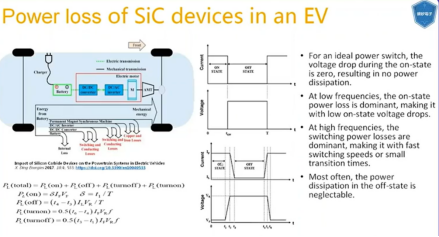
What are the highlights of the silicon carbide power module in an ideal car?.
The silicon carbide power module of Ideal Automobile has high power density. Through multi component integrated design, the volume of the motor controller is compressed to within 4L, and the power density reaches 62kW/L. This indicator is at the leading level in the industry, effectively reducing the volume and weight of the electric drive system, optimizing the vehicle space and energy consumption. Its energy conversion efficiency is also very high, making it more effective in utilizing electrical energy and reducing energy loss compared to similar products in the market. This is due to the low loss characteristics of silicon carbide materials themselves and the optimization of module design for ideal cars. Moreover, the silicon carbide power module of an ideal car has strong reliability. It adopts sintering process and pressure bonding connection from the chip to the substrate, which enhances the mechanical strength and electrical performance of the module and can adapt to the complex use environment and working conditions of the car.
In terms of research and development, production, and application, Ideal Automobile and Hunan Sanan Semiconductor jointly established Suzhou Sko Semiconductor Company to build a production base with an expected capacity of 2.4 million silicon carbide half bridge power modules, providing capacity guarantee for large-scale applications. Set up research and development centers in Munich, Germany and Singapore respectively to prepare for self-developed silicon carbide power modules. Meanwhile, Ideal Auto has also signed a long-term supply agreement with STMicroelectronics (ST). STMicroelectronics' third-generation 1200V SiC MOSFET advanced technology has industry-leading process stability, performance, energy efficiency, and reliability, which will provide strong support for Ideal Auto's silicon carbide power modules. Its first pure electric vehicle, the Ideal MEGA, has applied this technology. STMicroelectronics' (ST) SiC devices improve performance and efficiency through higher switching frequency, breakdown voltage, and thermal resistance. These are particularly important characteristics required for pure electric vehicles at higher operating voltages. Ideal Auto is adopting ST's advanced third-generation 1200V SiC MOSFET in its upcoming 800V pure electric vehicle platform traction inverter to ensure industry-leading process stability, performance, efficiency, and reliability.
Brake by Wire
What is Brake by Wire?
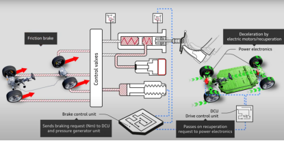
Wire controlled braking is a technology that uses electronic signals instead of traditional hydraulic or mechanical methods to transmit braking commands. The system captures the driver's braking intention through sensors and uses electrical signals to drive motors or electro-hydraulic actuators, achieving the generation and distribution of braking force. Its core feature is hydraulic free or semi hydraulic hybrid to improve the braking accuracy and response speed of the vehicle. This technology represents a crucial step in the transition of automotive braking systems from mechanization to electrification and intelligence, and has broad application potential, especially in the fields of electric vehicles, hybrid vehicles, and autonomous driving vehicles
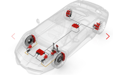
The basic components of the wire controlled braking system include the driver input system, electronic control unit (ECU), actuator, wire controlled network, and redundancy and safety modules. The driver input system captures the driver's braking intention through pedal displacement and force sensors, while providing force feedback to simulate traditional foot feel; ECU, as the core control unit, performs signal processing, dynamic braking force distribution, and generates driving instructions for the executing mechanism; The executing mechanism includes motor-driven clamps or electro-hydraulic servo actuators, which are directly responsible for generating and applying braking force; The wire control network connects system components based on high-speed communication protocols such as CAN or FlexRay to achieve efficient signal transmission; The redundancy and safety modules ensure the reliability and safety of the system in abnormal situations through multi-channel communication, independent power management, and backup braking mechanisms.
What is the difference between traditional braking and wire controlled braking?
The hydraulic brake system of traditional fuel vehicles involves pressing the brake pedal, which then pushes the vacuum booster. The vacuum booster then pushes the brake master cylinder to generate brake hydraulic pressure, which controls the brake calipers to apply the brakes.
Wire control technology is electrical control technology, which replaces traditional mechanical systems with precise electronic sensors and electronic actuators. Wire control technology replaces vacuum boosters and electric vacuum pumps with motors. When the brake pedal is pressed, the wire controlled braking system uses electric control brakes and sensors to monitor the force of the driver pressing the brake pedal. Then, the control unit of the system sends a message to the electric pump to generate the required pressure to slow down the car or completely stop it.
What is the physical basis and working principle of wire controlled braking?
Basic physical model:
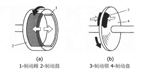
In the online control system, the generation of braking force is based on the principle of tribology, and its core formula is:

F: Braking force, provided by the frictional force between the friction material (brake pads) and the brake disc.
μ: Friction coefficient, influenced by the material properties, temperature, and surface conditions of brake pads and discs.
N: Normal pressure, applied by the actuator (motor or electro-hydraulic actuator).
System dynamic modeling:
In online control systems, dynamic behavior can be described using state space models or transfer functions. The following is the form of the transfer function:

G (s): Dynamic response of the braking system.
K: Gain, representing the ratio of braking force output to input signal.
τ: Time constant, reflecting the response speed of the system.
In dynamic modeling, the input is the driver's braking intention (pedal displacement or force), and the output is the actual braking force. Key parameters include response time, delay, braking linearity, etc.
Working principle of wire controlled braking:
1. Driver's braking intention collection
When the driver steps on the brake pedal, the sensor captures information on pedal displacement and pedaling force.
The input signal is transmitted to the ECU through the signal conditioning module.
2. ECU dynamic calculation
OECU calculates the required braking force based on input signals and real-time vehicle operating conditions (such as vehicle speed and load distribution).
Utilize dynamic braking force allocation algorithm to determine the braking force of each wheel.
3. Apply braking force to the actuator
The ECU generates a driving signal to control the actuator (such as a motor-driven caliper) to apply normal pressure N to the brake disc.
The braking force F is immediately generated through friction, causing the vehicle to decelerate.
4. Closed loop feedback control
The system has built-in sensors that monitor the deviation between the braking force and the target value in real-time.
ECU adjusts the action of the actuator through feedback algorithms (such as PID control) to ensure that the braking force accurately matches the driver's intention
Steer-by-Wire
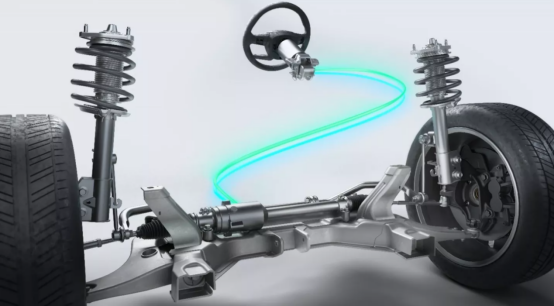
Steer by Wire (SBW) is an innovative automotive steering system that replaces traditional mechanical or hydraulic connections with electronic signals and electromechanical devices to achieve precise control of wheel direction. This technology is an important manifestation of the automotive industry's development towards intelligence, electrification, and automation, especially suitable for electric vehicles and autonomous driving vehicles.
What is the working principle of wire controlled steering?
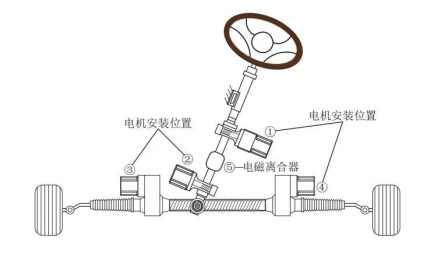
The wire controlled steering system eliminates the traditional steering shaft, gear rack, and hydraulic components, with electronic signals and motor drive as the core. The driver's steering input is transmitted to the actuator through electronic signals, directly controlling the steering angle and steering force of the wheels.
Its key components include:
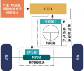
1. Steering angle sensor: When the driver turns the steering wheel, the sensor detects the steering angle and speed in real time, converts the data into electronic signals, and sends them to the control unit.
2. Electronic Control Unit (ECU): As the "brain" of SBW, ECU receives steering wheel angle signals and dynamic information such as vehicle speed and tire status, and calculates the optimal wheel angle and steering force through algorithms.
3. Execution mechanism: The electric actuator installed on the axle or tire controls the steering angle of the wheels according to the instructions of the ECU, accurately adjusting the direction of the vehicle.
4. Feedback device: In order to maintain a familiar "road feel" for the driver, the system simulates the hand feel and damping changes of traditional mechanical steering through motors and simulated feedback devices.
In the wire controlled steering system, the input of the steering wheel is captured by the steering angle sensor and torque sensor and converted into electronic signals, which are transmitted to the electronic control unit (ECU). ECU calculates the target wheel steering angle based on steering input, vehicle dynamic status (such as vehicle speed, acceleration, etc.), and system algorithms. The actuator (such as a motor or electro-hydraulic actuator) achieves the actual steering of the wheels.
What are the advantages of wire controlled steering
In terms of driving experience, the steering control of wire controlled steering is more precise and sensitive, because the steering wheels are precisely controlled by the electrical signals of the electronic controller, and the transmission ratio of the system is variable; For car companies, using steer by wire will reduce the complexity of the vehicle system structure; In addition, line control and autonomous driving can cooperate more deeply, as the direction of vehicle travel can be controlled by electrical signals.
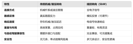
Comparison between steer by wire and traditional steering systems
Fully Active Suspension
What is fully active suspension?
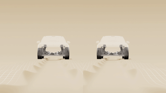
Fully Active Suspension (FAS) is a high-performance suspension system that actively controls the dynamic behavior of the vehicle suspension system through an external energy source, thereby improving the comfort, handling, and stability of the vehicle under different operating conditions. Unlike passive suspension or semi-active suspension, fully active suspension can actively apply force based on real-time data collected by sensors to suppress vehicle vibration and dynamic displacement.
Fully active suspension detects vehicle status (such as vehicle speed, acceleration, suspension displacement, etc.) through sensors, transmits data to the electronic control unit (ECU), and then drives actuators (such as electric motors or hydraulic actuators) to generate control force, thereby achieving dynamic decoupling between the wheels and the vehicle body.
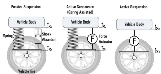
What is the system composition of fully active suspension?
The fully active suspension system consists of multiple sub modules, including high-precision sensors for real-time monitoring of vehicle dynamic status (such as acceleration sensors, displacement sensors, wheel speed sensors, and tilt angle sensors), electronic control units (ECUs) responsible for calculation and control, high-performance actuators for executing control forces (such as hydraulic actuators, electric actuators, or electro-hydraulic hybrid systems), and power sources (electric or hydraulic systems) that provide external energy support for the actuators. The vehicle status data collected by sensors is transmitted to the ECU through a high-speed communication network. The ECU calculates the optimal control force through advanced control algorithms, and the actuator actively adjusts the suspension stiffness and damping characteristics based on this, thereby achieving dynamic performance optimization of the vehicle under different working conditions
What is the working principle of fully active suspension?
The working principle of fully active suspension is based on active force control technology, which collects real-time dynamic information of the vehicle through sensors (such as body acceleration, suspension displacement, wheel speed, and road input), and transmits the data to the electronic control unit (ECU). ECU combines vehicle dynamics models and uses advanced control algorithms such as linear quadratic regulators, robust control, or adaptive control to calculate the optimal active control force required for the suspension system in real time. The actuator (such as electric or hydraulic actuator) quickly applies precise force to the suspension system according to control instructions, achieving dynamic adjustment of the motion between the vehicle body and the wheels, effectively suppressing vibration, improving wheel contact, and optimizing the vehicle's handling stability and ride comfort
Fully active suspension adjusts the dynamic characteristics of the vehicle in real-time through a series of sensors, control algorithms, and actuators. Its core components include:
1. Sensor system:
Vehicle acceleration sensor: monitors the vertical movement of the vehicle body to identify road roughness and vehicle vibration.
Wheel displacement sensor: measures the relative motion between the wheel and the vehicle body.
Speed and steering angle sensors: provide vehicle driving status information to ensure suspension dynamic response is consistent with driving requirements.
2. Electronic Control Unit (ECU):
ECU is the "brain" of fully active suspension, which analyzes sensor data to calculate real-time suspension adjustment parameters (such as support force and damping force) to optimize vehicle handling and comfort.
3. Executing agency:
The core of fully active suspension is the actuator, which usually takes the following form:
Electric actuator: Provides precise adjustment force through the motor, with fast response.
Hydraulic actuator: using a hydraulic system to provide a large adjustment force, suitable for heavy-duty vehicles.
The actuator actively applies force according to ECU instructions, adjusting the support force and damping characteristics of the suspension.
Increase the layout of AI
The company regards the German research and development center as an important support for its core AI (artificial intelligence) strategy.
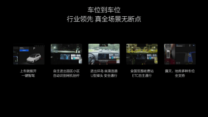
Ideal Auto stated that nearly half of its current R&D investment is dedicated to the development and application of AI technology, and is committed to building a complete system capability in the AI field.
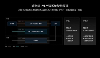
With the clear focus of competition for intelligent vehicles in 2025, cities such as Wuhan and Beijing are about to open up L3 level autonomous driving on the road, ushering in a crucial battle for advanced intelligent driving. On January 16th, Ideal Auto released the AD Max V13.0 version of its intelligent driving system through OTA 7.0, providing end-to-end+VLM technology trained on 8 million video data segments, bringing a nearly zero takeover and seamless seamless driving experience across all scenarios. Since the transition from OTA 5.0 to BEV architecture and the launch of city NOA, Ideal has completed 12 major updates to AD Max, building a clear independent version iteration path and demonstrating its leading advantage in intelligence. By the end of 2024, the ideal NOA navigation intelligent driving mileage accounted for 70%, and AD Max delivery accounted for over 75% of vehicles priced over 300000 yuan. With rapid technological progress and product strength, Ideal has gradually shaped the market perception of "Ideal is Intelligent Driving".
The unique technological path of Ideal Intelligent Driving stems from a profound understanding of AI technology and user needs. Its "fast slow dual system" architecture imitates human driving logic. System one adopts an end-to-end architecture to cope with conventional road conditions, while System two integrates image and text information through a multimodal large model (VLM) to provide more comprehensive environmental cognitive capabilities. The intelligent driving algorithm has demonstrated the potential of data-driven AI model evolution, from initially relying on 800000 video data segments to being able to evolve through complex scenes such as roundabouts with 1 million segments of data. Ideal Auto invests billions of yuan in research and development every year, with nearly 50% of it dedicated to the AI field. The goal is to elevate the foundation of the big language model to the top three in the industry and integrate VLM to thoroughly understand vision and language. Ideal Auto believes that in the future, AI driven intelligent cars will be centered around "car and home", providing efficient and humane services, thus achieving the mission of AI connecting the physical and digital worlds.
Ideal Automobile Company stated that the next step will continue to explore the globalization of research and development layout, absorb global R&D talents from different backgrounds, and build a diversified talent team. Through the new research and development center, the car manufacturer also aims to gain a better understanding of the European market and develop products that are more in line with European automotive regulations and consumer preferences.
The R&D center marks the official launch of Ideal Automotive's global strategy. It will also become the cornerstone of our core AI strategy, with nearly half of our R&D investment currently dedicated to AI technology, "said Ma Donghui, CEO of Ideal Automotive, in a statement
Note: The data and images cited in the article are sourced from the internet


