Technical Analysis of Intelligent Automotive EMB Electronic Control Mechanical Braking System
Before the development of new energy vehicles, the braking systems of traditional cars mostly used vacuum assisted hydraulic braking systems. With the rapid development of new energy vehicle technology, the braking system, as a key component of car safety, is also constantly developing and evolving, especially with the increasing demand for intelligence in cars. The wire controlled braking system has become an essential technology for car braking systems. In the field of intelligent electric vehicles, it effectively solves the problem of vacuum assist deficiency and can perfectly achieve energy recovery, greatly improving energy utilization efficiency. In terms of performance, wire controlled braking greatly shortens the braking response time. The traditional vacuum assisted hydraulic braking system has a response time of about 300-500 milliseconds, while the wire controlled braking system can shorten this time to less than 100 milliseconds, providing a faster guarantee for driving safety. The wire controlled braking system includes two types: EHB Electro Hydraulic Braking System and EMB Electro Mechanical Braking System. EHB has been widely used in intelligent electric vehicles with relatively mature technology, while EMB is currently in the experimental stage and has not yet been mass-produced. This article mainly introduces the EMB electronic mechanical braking system.
The EMB electronic control mechanical braking system abandons the complex hydraulic or pneumatic pipelines in traditional braking systems and directly generates braking force through motors, achieving complete decoupling of the braking system. The structure is more compact, the response is faster, and the execution efficiency is higher, which is conducive to the development of chassis domain control and intelligent driving technology. However, due to the complexity of technology and the need to improve reliability, large-scale production has not yet been possible.
1、 Working principle and system composition of EMB
The EMB system architecture adopts a central controller+four-wheel independent caliper controller architecture. The four-wheel caliper controller serves as a redundant backup of the central controller, providing backup braking arbitration and braking force distribution functions. When the central controller fails, the wheel end controller can control the brake actuator to output braking force according to the instructions of the motor controller. When the driver steps on the brake pedal, the pedal position sensor transmits a signal to the central controller, which accurately calculates the required braking force based on various sensor data such as vehicle speed and load. Then, the central controller sends control commands to the motors of each wheel, which convert rotational motion into linear motion through a reduction mechanism, pushing the brake pads to press the brake discs, thereby generating braking force. During the braking process, sensors monitor the braking status in real-time and provide feedback to the central controller to achieve precise braking control and adjustment.
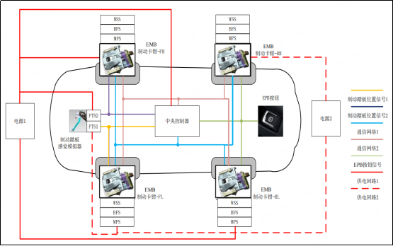
Figure 1: EMB system architecture of a certain supplier
The EMB system mainly consists of a pedal sensation simulator, a central controller, a wheel end braking force control system, wheel speed sensors, clamping force sensors, motor position sensors, EPB switches, and electronic brake calipers.
① Pedal Sensation Simulator (PFS)
Used for simulating brake pedal sensation, detecting brake pedal displacement or force, and providing vehicle wake-up signals, including two brake pedal position sensors PTS. The pedal ratio, pedal stroke, pedal initial force, damping, etc. of the pedal sensation simulator can be adjusted according to the pedal sensation requirements of different vehicle models to ensure a more comfortable pedal sensation. The overall durability life reaches 2.2 million times or more.
The pedal sensation simulator and EPB switch can be directly connected to the central controller module. When the driver triggers the brake pedal switch while driving, the brake information is obtained through the pedal sensation simulator, and then directly transmitted to the EMB central controller. The EMB central controller then calculates the first brake torque data that needs to be applied to each wheel and assigns all the first brake torque data to the corresponding wheel end controllers; Similarly, when the driver triggers the EPB switch, the parking request is directly transmitted to the EMB central controller, which then calculates the first braking torque data that needs to be applied to each wheel and assigns all the first braking torque data to the corresponding wheel end controllers. By connecting the pedal sensation simulator and EPB switch to the EMB central controller, the response time of the car's braking has been improved.
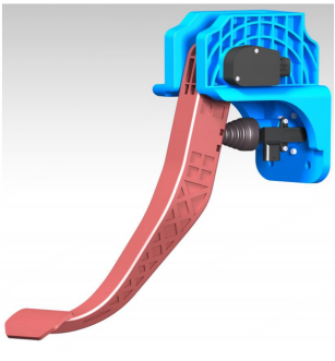
Figure 2: PFS structure diagram of a certain supplier
② EMB Central Controller (VCCD)
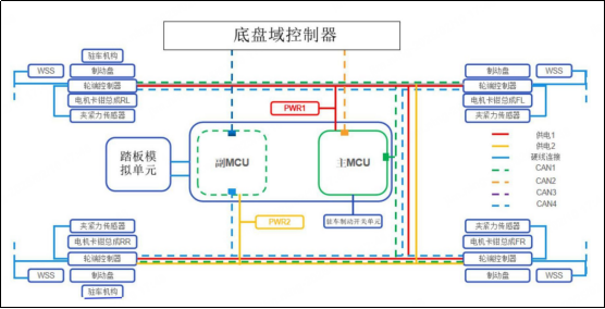
The central controller is responsible for receiving signals, determining the driver's intention, and outputting braking commands for decision-making in the braking system to ensure vehicle stability control. In general, the central controller control module includes a main MCU unit and a sub MCU unit. The main MCU unit receives braking data and calculates the first braking torque data that needs to be applied to each wheel. When the main MCU unit fails, the sub MCU unit serves as a backup and receives braking data through the sub MCU unit and calculates the first braking torque data that needs to be applied to each wheel.
By setting up the main MCU unit and the sub MCU unit, and connecting them to other modules through the first communication network and the second communication network respectively, the fault tolerance of the central controller has been increased. When the main MCU unit in the central controller fails and cannot work, or when the first communication network fails, the auxiliary MCU unit can take over the work of the main MCU unit through the second communication network, ensuring the smooth operation of the EMB control module and avoiding the situation where the vehicle enters the fault due to the main MCU unit failure.
③ Wheel end braking force control system (WBC)
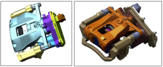
Used for the execution of wheel end braking force, as well as decision-making and execution of backup braking, including EMB wheel end caliper controller+electronic brake caliper.
The wheel end caliper controller is electrically connected to the motor caliper assembly and the central controller, used to receive the first braking torque data and control the electronic brake caliper assembly to apply the braking torque corresponding to the first braking torque data to the wheels.
④ Wheel Speed Sensor (WSS)
Wheel speed and vehicle speed detection, electrically connected to the wheel end controller, used to measure the speed of each wheel, obtain the speed data of each wheel, and transmit the speed data of each wheel to the central controller through the wheel end controller.
⑤ Clamping force sensor (BFS)
Electrically connected to the wheel end controller, used to sense the clamping force of the wheel end clamp, measure the clamping force of the motor clamp assembly, obtain clamping force data, and transmit the clamping force data to the central controller through the wheel end controller, making the clamping force control more accurate and used for diagnosis.
By setting a clamping force sensor, detect whether the difference between the clamping force applied by the motor caliper assembly and the clamping force data corresponding to the braking torque received by the wheel end controller is within the error range. If it is within the error range, it indicates that the motor caliper assembly is not damaged and can work normally. If the difference is outside the error range, it indicates that the motor caliper assembly may be damaged and the driver needs to be reminded to repair or inspect the vehicle.
⑥ Motor Position Sensor (MPS)
Used for sensing motor angle and speed, for motor torque control and diagnosis.
⑦ EPB switch (EPB-SW)
Monitor the driver's parking request and use it as a backup braking excitation source. The driver sends parking and parking release signals to the vehicle CAN network through the EPB parking button switch. The EMB central controller module receives the parking or release signal through the CAN network and sends a parking or release command to the EMB caliper controller through a private CAN. The EMB caliper controller controls the left and right rear EMB calipers to complete the parking, and at the same time, the EMB caliper controller feedbacks the parking status to the central controller to complete the parking.
⑧ Power module
It consists of a car battery and a backup battery. The car battery is the main battery used to supply power to the central controller and wheel end controllers through the first power supply line. The backup battery is used to supply power to the central controller and wheel end controllers through the second power supply line when the car battery fails. When the wheel end controller controls the motor caliper assembly to apply braking torque to the wheels, in order to avoid the situation of insufficient battery power in the car, a backup battery is set up to prevent brake failure due to insufficient battery power in the car.
2、 Advantages and Challenges of EMB Technology
EMB has technological advantages such as faster response speed, shorter braking distance, better braking experience, simplified system, and easy integration and intelligence.
(1) Faster response speed and shorter braking distance. Compared with traditional hydraulic braking systems, EMB systems eliminate the transmission delay of hydraulic oil and directly use mechanical transmission mechanisms to convert the rotational force of the driving motor into linear motion, forming an electric braking device with a pressurized piston. Due to the fast response characteristics of motors, they have a faster response rate than hydraulic brakes, and can obtain accurate motor torque from current sensors and independently control the braking force of each wheel. Due to the ability of the motor to quickly respond to instructions from the EMB central controller, the rapid establishment of braking is achieved, greatly reducing the braking distance and improving braking safety.
(2) Better braking experience and high braking accuracy. The transmission speed of electrical signals is much faster than that of hydraulic systems, and the delay of brake commands from sensors to actuators is significantly reduced (up to 100ms). The central controller can independently and accurately control the braking force of each wheel based on various driving conditions and vehicle status, achieving advanced braking functions such as anti lock braking (ABS), electronic stability program (ESP), etc. Each wheel is independently controlled to achieve better torque distribution (such as ABS, ESC, TCS function integration), thereby improving the vehicle's handling stability.
(3) A more simplified system with a simple and compact structure. The elimination of complex hydraulic pipelines and components makes the braking system structure of the vehicle simpler, occupies less space, facilitates the overall layout and lightweight design of the vehicle, reduces the risk of leakage, and also reduces the complexity and maintenance costs of the system.
(4) Easy integration and intelligence: The EMB system is naturally suitable for integration with other electronic systems of the vehicle, and is deeply integrated with the vehicle control system to meet the requirements of L3+level automatic driving for fast and accurate braking. It can better realize the intelligent control of the vehicle and provide strong support for the development of autonomous vehicle in the future.
Despite the numerous advantages of EMB systems, there are still technical challenges that need to be overcome. Firstly, it is necessary to develop motors and their drive systems with high power density and reliability to meet the requirements of high torque and fast response during braking, while also ensuring stable operation in various harsh environments. Secondly, the current cost of EMB systems is relatively high, mainly due to their advanced electronic components and precise manufacturing processes; Reducing costs and making it competitive in the market is the key to promoting its application.
3、 Conclusion
With the rapid development of the automotive industry towards electrification, intelligence, interconnectivity, and personalization, L3 and above intelligent driving electric vehicles have put forward higher technical requirements for the entire vehicle braking system. Faster response speed, shorter braking distance, independent four-wheel control, multi scenario torque vector control, complete decoupling of software and hardware, full-time electric drive, agile iteration, precise control, system safety redundancy, etc. are all things that traditional hydraulic systems cannot meet at present. EMB technology, with its rapid response, high-precision control, lightweight and intelligent potential, is driving the transformation of automotive braking systems towards comprehensive electrification and wire control. With the maturity of technology and cost reduction, EMB is expected to become one of the core technologies for the next generation of intelligent vehicles.
Note: The data and images cited in the article are sourced from the internet


