Technical analysis and future development of flat wire winding for drive motor
1.Introduction
As the core power source of electric vehicle, drive motor needs to meet the design requirements of high power density, high efficiency, high reliability and lightweight. The U.S. Department of Energy's 2025 plan calls for increasing the power density of drive motors from 1.6kW/kg in 2020 to 5.7kW/kg. It can be seen that the development of high-performance drive motors has become the focus of new energy electric vehicles, which is of great significance to national economic development and environmental protection.
As we all know, the stator winding is the power heart that drives the motor, which usually refers to a symmetrical circuit connected by multiple coils or groups of coils through different winding methods. The stator winding method has two kinds of flat wire winding and round wire winding, the slot filling rate of flat wire winding can reach more than 60%, while the round wire is only about 40%, so it is more excellent in efficiency, power density, cost and noise, etc., and has been more and more widely used in electric vehicle drive motors in recent years.
At the same time, in order to improve power density and driving range, the drive motor speed continues to increase, the electric drive system bus voltage level continues to improve, from 600V to 800V, and even some car companies began to plan more than 900V voltage platforms, the superposition of these factors have brought more challenges to the flat wire winding.
2.Topology and design of flat wire winding
(1)flat wire winding structure and classification
According to the different structure, the flat wire winding of the motor is usually divided into five types, such as overlapping winding, Hair-pin, I-pin, X-pin and continuous wave winding. These different forms of flat wire winding have their own characteristics in coil shape, welding structure and stator embedding mode, the specific details are shown in the following table. In the assembly process, these windings show significant differences. Stacked winding is often used in large generators, and Hair-pin winding, because of its shape similar to "hairpin", also known as "hairpin winding", is the most common and mature manufacturing process of flat wire winding form. It is widely used in the Toyota Prius 2017, Tesla Model Y, BMW i7 and other vehicles, thanks to the existing molding and welding equipment, to meet their mass production needs. The structure of Hair-pin winding is similar to that of other flat wire winding in the slot, but the difference of end length is mainly due to the difference of end welding process. For "pin" flat wire windings, such as I-pin and X-pin, they usually have a turn of coil inserted into the slot axially, and then transposed and welded at the end, so a large number of solder joints are required to maintain the electrical connection between the coils. In particular, I-pin and X-pin winding, because both ends need to be welded, the number of solder joints is almost twice that of Hair-pin. It is worth noting that both Hair-pin and I-pin use a straight line extension section welding process, resulting in a longer end. However, because the I-pin winding does not have the problem of stress rebound at the forming end, the conductor gap in the slot is smaller, thus improving the slot filling rate. According to relevant data, the slot filling rate of Hair-pin winding is 69%, while I-pin winding can reach 74%. As an improved version of the I-pin winding, X-pin significantly reduces the end length by 27mm compared to the I-pin winding by optimizing the end profile. At present, the winding has been applied to the drive motor of GAC Aean. As for the continuous wave winding, it has been formed before embedding the stator, almost eliminating the need for solder joints, but it is required to be embedded in the groove along the radial, which puts forward the requirement of open groove for the stator core design, such design tooth groove torque is large, and the winding automatic forming device is more complex.
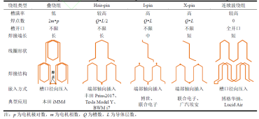
Generally speaking, Hair-pin winding tends to be used in current vehicle drive motors, while lap winding and continuous wave winding are rarely used in drive motors. Compared to these three common flat wire winding types, I-pin and X-pin windings exhibit a higher slot fill ratio advantage. However, they also face significant challenges: multiple solder joint designs increase process complexity and drive up the cost of automated molding and welding equipment. In addition, insulation debris easily generated during the welding process can seep into the cooling oil (ATF oil), posing a potential threat to the reliability of the gearbox. Therefore, although "pin type" flat wire winding has its advantages, there are still many difficulties in the process and technology. In contrast, the non-solder joint continuous wave winding form has undoubtedly shown more significant advantages in simplifying the process, reducing the cost and ensuring the reliability of the system.
(2)flat wire winding design principles
Due to its large conductor cross section, flat wire winding is susceptible to high frequency eddy current effect and armature reaction, which leads to the uneven distribution of conductor current density in each layer and different pole phase slot, and thus produces impedance differences. In order to prevent circulation between branches, the design of the flat wire winding should follow the following transposition principle: If the number of parallel branches a=1, a single branch must traverse all conductor layers in each pole phase slot. When the number of parallel branches a is greater than 1 and the number of slots per pole per phase q is greater than 1, ensure that the number of conductors in each branch is the same based on the above conditions. Keep the winding end length as consistent as possible and reduce the number of unequal span windings to optimize the overall performance.
At present, the flat wire winding motor generally adopts distributed winding structure, where the q value is usually 2 or 3. The larger the q value, the better the sinusoidal degree of the back potential. For example, the Tesla Model series adopts the design scheme of 6-pole 54 slots, but this is also accompanied by the increase of winding end length and the improvement of wire insertion difficulty. In contrast, Toyota Prius series and BMW i series choose q=2 solution.
It can be seen that the flat wire winding is a kind of winding with complex transposition structure, and the interturn conductor needs to combine the end welding and forming technology to form a continuous coil. Generally, BusBar connectors are used to realize electrical connections between branches. The BusBar structure must meet the design requirements of high strength, high temperature and high pressure resistance.
3. AC loss problem of flat wire winding
(1) flat wire winding loss generation mechanism and influencing factors
When a conductor is subjected to alternating current or an alternating magnetic field, eddy current effects are triggered. A single conductor will exhibit a skin effect, while two adjacent conductors will have a proximity effect. However, in the actual motor, the leakage magnetic field in the slot is complicated, which combines the armature magnetic field and the rotor magnetic field components. Unfortunately, the analytical calculation models of most winding losses often ignore the role of rotor magnetic field, which leads to the limitation of loss calculation accuracy. As shown in the figure, the distribution of conductor current density with or without rotor magnetic field is shown under the condition of armature current of the same amplitude and frequency. It is found that the permanent magnet field of the rotor has a significant influence on the leakage field of the notch, and a large number of radial components are introduced, which makes the current density of the conductor present an uneven distribution in both radial and tangential directions. Further research shows that when the slot size is large, the loss caused by the rotor magnetic field may even exceed the loss caused by the stator armature field. Therefore, the influence of rotor magnetic field can not be ignored when evaluating AC loss of flat wire winding.

(2)Ac loss suppression method for flat wire winding
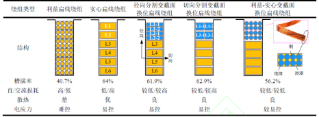
From the perspective of topological structure, the current main strategies to restrain AC loss in flat winding include: increasing the number of conductor layers, using the design of conductors away from the notch, implementing split winding (such as unequal area winding), applying the interstrand transposition Leeds flat winding, and hybrid winding, etc., as described in the table. Taking the 10-layer flat wire winding used by Tesla in the 2019 Model Y series of vehicles as an example, although the number of layers can be as many as 10 layers, the multi-layer design poses a challenge to the slot filling rate, increasing the manufacturing complexity and cost. The core of the strategy of increasing the number of layers and dividing the winding is to reduce the radial size of the conductor and effectively suppress the AC loss caused by the tangential leakage field, but the effect on the radial leakage field is limited. Although the design away from the notch can avoid the conductor being affected by the slot leakage magnetic field, it sacrifices the slot filling rate, which is unfavorable to the improvement of the motor power density. Litz flat wire winding with interstrand transposition can inhibit high frequency loss significantly, however, the process complexity is increased, and the interstrand insulation reduces the slot filling rate. The hybrid transposition flat wire winding adopts interstrand transposition flat wire at the slot while maintaining a high slot filling rate. The other layers retain the traditional solid flat wire, which realizes the low loss characteristic in the wide band domain. However, with the complexity of winding topology and the difficulty of manufacturing process, how to control the cost has become an urgent problem.
The following table lists the five main winding structures, with 6 layers (turns) of conductor as an example, while maintaining the size of the slot and single layer winding: including the conventional flat wire winding, the traditional round wire winding (including the interstrand transposition, also known as the Leeds flat wire), and the three types of winding that use the division and transposition structure in the two layers near the slot to avoid the slot leakage field. In view of the rectangular conductor structure is not conducive to the interstrand braid transposition, the researchers proposed an innovative scheme - Leeds solid variable section transposition flat wire winding, which replaces the notched solid flat wire with Leeds flat wire to simplify the transposition process.
It is worth noting that the loss of Leeds flat wire winding is the lowest in high frequency band, and the opposite is true in low frequency band. Solid flat wire winding characteristics are opposite. Although the radial or tangential split variable section transposition flat wire winding can suppress high frequency and keep low loss, the loss suppression effect in the wide band domain is still not as good as that of the Litz-solid variable section transposition flat wire winding. When the operating frequency is 1200Hz, the AC-DC loss ratio of the flat wire winding is as high as 10.2, while that of the Litz-solid variable section transposition flat wire winding is only 2.12, which shows remarkable superiority.
To sum up, the core technical characteristics of the existing AC loss suppression scheme for flat wire winding are realized by splitting the notched conductor and implementing the interstrand transposition, the fundamental purpose of which is to effectively suppress the loss of flat wire winding near the notched area. This method not only ensures a high slot filling rate, but also realizes the design goal of low loss in the broadband domain. However, as the structure of flat wire winding becomes more and more complicated, the key to its successful application and popularization is to solve the processing problems of this kind of winding.
4.Flat wire winding motor heat and cooling problems
(1) flat wire winding motor heat distribution characteristics
Limited by the heat dissipation mechanism, the traditional shell water cooling technology in the application of round wire winding, the highest temperature often appears at the winding terminal. However, under high frequency operating conditions, the energy loss of the conductor in the slot is not uniform, especially in the slot position, the loss is the most serious. It is worth noting that by implementing oil injection cooling at the end of the winding, the temperature in this area is significantly reduced, but this also reveals that the notch side becomes a new high temperature concentration area. In order to deal with the unique temperature distribution of the flat wire winding motor, two strategies can be adopted: one is to use the active loss control technology to reduce the heat output of the heat source; The second is to strengthen the heat dissipation effect of the local high temperature points in the groove through the fine cooling layout design, which not only improves the heat load capacity of the winding, but also promotes the increase of the overall power density of the motor.
(2) oil cooling scheme
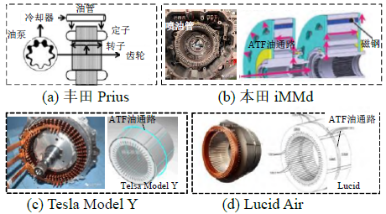
The Toyota Prius innovatively introduced the end-tubing injection cooling mechanism, which achieved a significant increase in cooling efficiency by fine-tuning the injection rate and nozzle layout. In contrast, Honda iMMd adopts rotary centrifugal lubrication technology, whose core is to use a hollow shaft to directly inject lubricating oil into the high-speed rotating rotor, and with the help of powerful centrifugal force, the oil is effectively distributed to the end of the winding to achieve efficient heat dissipation. Tesla and Lucid brands have adopted the slotted or perforated design of the stator core, and demonstrated different technological paths by introducing ATF (automatic transmission fluid) directly to cool the end of the winding. China's BYD DM-i, SAIC Zhiji L1, Huawei DriveONE and other motor products also follow the trend of oil cooling technology and adopt a similar scheme. However, a common challenge for these oil cooling systems is the quality control of ATF oils, as they not only serve as a cooling medium, but also perform lubrication duties in precision gear systems, placing high demands on oil purity. Particularly complicated is that the high temperature generated by the end welding process of the flat wire winding can easily lead to the degradation of the insulation material, forming debris contaminated oil, which will seriously threaten the health and overall reliability of the gear system once the cooling system is circulated to the gear box. Therefore, to explore the perfect compatibility of insulation materials and ATF oil has become an urgent technical problem. In addition, the damping effect of cooling oil on high-speed rotating parts is also an important part of oil-cooled motor design, and how to effectively balance cooling and drag reduction has become another major technical challenge.
(3)Direct cooling solution in tank
Faced with the challenge of surge of winding load and uneven temperature distribution caused by the increase of power density of drive motor, especially the local overheating problem in the slot of flat wire winding, the direct in-slot cooling technology came into being. The current phase of the technology is mainly focused on fractional slot central-winding motors, because the winding layout allows sufficient space to be reserved in the slot for the arrangement of cooling channels. In contrast, the slot space utilization of the integral slot distributed flat wire winding motor is high, and the direct cooling implementation is more difficult. To overcome this limitation, researchers have proposed a variety of solutions. The research team of Marquette University in the United States has innovatively realized the hollowing design of flat wire winding through the integration of heat pipes and 3D printing technology, and has been successfully applied to the high-performance drive system of electric aircraft, reaching a high power density of 20kW/kg. The University of Sheffield in the United Kingdom explored the direct liquid cooling strategy of hollowing out the inside of the flat wire winding, although the manufacturing process faced the problem that the hollow conductor was prone to blockage at the bend. The research of the University of L 'Aquila in Italy focused on the optimization of the cooling layout, and its experimental results showed that the cooling water is cleverly arranged near the notch, while keeping the groove depth design unchanged, which can more effectively reduce the temperature rise and enhance the performance of the motor under high-speed conditions.
From the perspective of several typical cooling methods of existing vehicle drive motors, the housing water cooling scheme is widely used in the previous generation of motors, and the technology is relatively mature, but its cooling efficiency for local hot spots in the winding needs to be improved. The oil cooling scheme at the end of the flat wire winding has been widely accepted by the new generation of motors with its advantages of efficient cooling, but its cooling effect on the local hot spot in the groove is not ideal, and there are problems such as easy to be disturbed by insulation debris during welding. In contrast, the groove cooling and winding direct cooling method, because of its higher cooling efficiency, is gradually becoming an important development direction of high power density drive motor distributed cooling. It is particularly noteworthy that for the drive motor with integer slot distributed flat wire winding, the space in the slot is limited, and the hollow conductor or oil-immersed cooling technology is expected to be an alternative solution to this problem. However, complex cooling structure design is the difficulty of distributed cooling. Therefore, the winding direct cooling technology combined with advanced materials and 3D printing process is in urgent need of further research and exploration, in order to break through the existing technical bottleneck and improve the overall performance of the drive motor.
5.Future development
New high power density flat wire winding and its cooling structure, including unequal section flat wire winding, interlayer/slot/strand hybrid transposition flat wire winding and distributed direct cooling design, these innovative structures are difficult to achieve using traditional manufacturing methods, but 3D printing technology is expected to become one of the effective ways to achieve. However, the main challenge is high manufacturing costs. In the future, with the realization of mass production, this cost disadvantage is expected to be remedied. At the same time, for the windings manufactured by 3D printing technology, their electrical properties, mechanical properties and cooling channel sealing properties still need to be further studied and optimized to ensure that the windings achieve excellent levels of electrical properties and reliability.
(1)The problem of AC loss in flat wire winding is aggravated by the high speed of vehicle drive motor, so it is urgent to develop a new generation of flat wire winding topologies with low loss characteristics in wide frequency domain, such as variable section flat wire winding and segmented hybrid transposition flat wire winding. Based on the actual working conditions of the vehicle, it is necessary to carry out the wideband domain winding optimization design, aiming at proposing the next generation flat wire winding scheme with minimum loss under the working conditions of the vehicle, so as to achieve the goal of high efficiency and high power density of the drive motor. However, with the increasing complexity of winding structures, the problem of its manufacturing process has become a key challenge hindering its further development.
(2) the high loss density and its uneven distribution in the flat wire winding groove near the slot lead to local hot spots, improve the insulation thermal stress level, and then pose a threat to the reliability of the motor. Compared with traditional case cooling, in-tank cooling and direct winding cooling show higher cooling efficiency, which has become one of the prominent features of distributed cooling of high power density drive motors. The hollow conductor or oil-immersed cooling method is expected to further improve the power density of the flat wire winding of the vehicle drive motor. In addition, the integration of advanced materials and 3D printing process into the distributed direct cooling technology of winding still needs to be further explored and studied.
(3) Under the high frequency and high dv/dt excitation conditions of SiC inverter, the inter-turn insulation voltage stress level of flat wire winding is significantly increased, resulting in the risk of initial discharge of insulation. In order to reduce the voltage stress between turns, improve the reliability of flat wire winding, and ensure the insulation safety, it is necessary to start with the winding structure optimization and insulation enhancement design. In particular, it is necessary to further study the high-precision calculation method of voltage stress between turns of flat wire winding, and consider the initial discharge measurement technology under the comprehensive action of many factors such as electricity, heat and pressure. In addition, it is also very important to explore new low voltage stress winding transposition topology and develop new insulation materials that are resistant to corona, heat and oil. The ultimate goal is to develop highly reliable flat wire windings suitable for future automotive drive motors with high voltage grades of 800VDC and above.
(4) 3D printing manufacturing technology provides an effective solution for the manufacture of new complex structure flat wire winding. However, the design of these motor windings and their insulation materials differs from traditional structural components in that they require high electrical conductivity, high thermal conductivity and high dielectric capacity. Therefore, there are still many challenges in integrating 3D printing technology into the preparation process of such new structural windings and achieving low-cost, standardized production. Although most 3D printed windings are still in the prototype development stage, it is foreseeable that the flat wire winding technology with high power density and high reliability is expected to be realized through 3D printing technology in the future.
Note: This article cites data and images from the Internet


